WORKSTATIONS & STORAGE EQUIPMENT
From the beginning to the end of product production, we offer you workstations that shape the workflow. We design the production process with customized solutions for your needs. A complex number of possibilities simply leads you to your goal.
Cross-linking
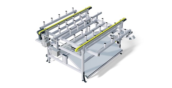
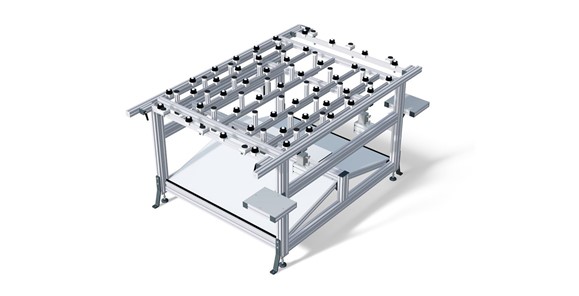
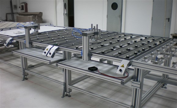
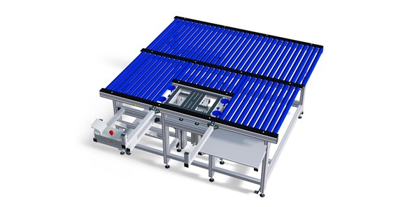
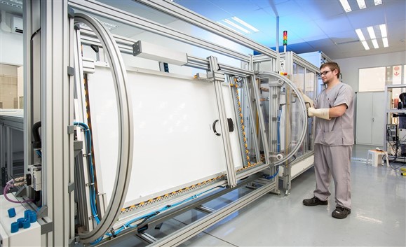
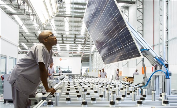
Manual or automatic transport of glasses, plates and frames. Two mirrors and a work area light are located on the substructure of the welding table to allow workers to see the underside of the unit. As a second step, the second EVA and tedlar film can be manually placed on this table.
Image 1: Soldering table width 1300mm single with belt conveyor
Image 2: Soldering table width 1300mm
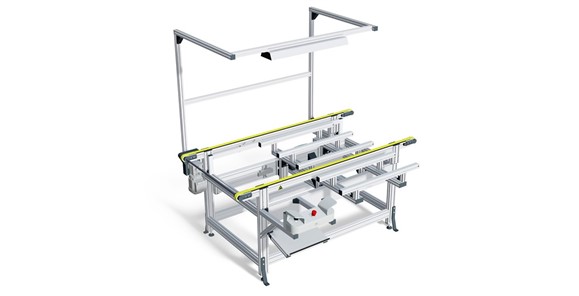
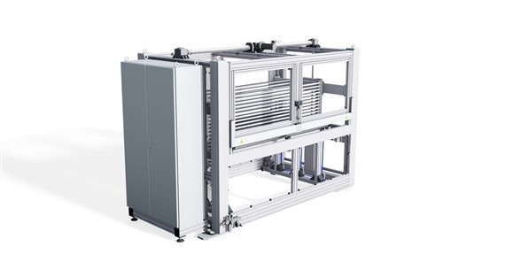
Trimming
Machining of plastic edges. Unit transport via rollers or automatic toothed conveyor belt. The unit is fixed with suction cups under vacuum. Now the sheet can be cut freely. The working height for machining is freely adjustable. After processing, the unit returns to its original position and can be moved.
Image 1: Trimming station with belt conveyor SEL
Image 2: Trimming station with ball castor
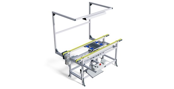
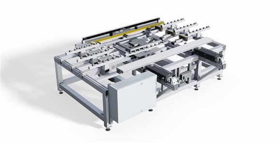
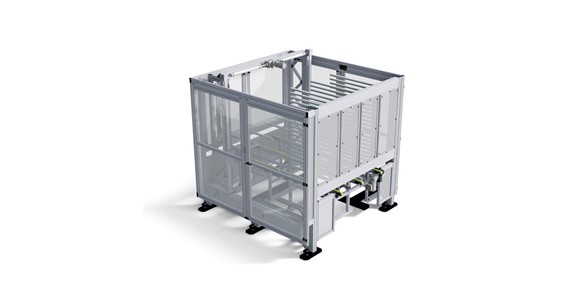
Box mounting
The first unit is automatically transferred to the toothed conveyor belt. When the end position is reached, the first unit is raised via a 2-hand switch. After machining is complete, the operator can lower the first unit by releasing it (two-hand control).
Image 1: J-box mounting
Image 2: J-box mounting 1300 mm
Image 3: J-box mounting with conveyor LEL

Framing station
Frame stations are used to place frame on the unit. The unit is transported either semi-automatically (on rollers) or automatically (on a conveyor belt) to the frame station. There the frame parts are manually placed in the unit. Depending on the choice of frame parts (with screw corners; with corner connection corners), the station can be adjusted individually. Equipped with a turntable, lifting station and vacuum cups, the unit is easy to move. The operator can now easily connect the parts to the unit.
Image 1: Framing station EVO 4 semi-automatic
Image 2: Framing station semi-automatic with loading handling and automatic module transport
Corner angle mounting device
The frame from profiles with fitted corners (dimensions with tolerances to be specified in advance) is inserted into the device. The connection process is activated by a two-hand pneumatic control. The roller moves forward as long as both hands remain activated.
The force is regulated via a separate pressure regulator. The length of the frame profiles is done by manual clamping (lengths 660 mm - 1100 mm, others on request).
Two-handed pneumatic control is built into a plastic housing.
The system mechanically ensures that the installed corners are always symmetrical and pressed to the specified dimension regardless of the length of the inserted frame profile.
Image 1: Corner key preparation station
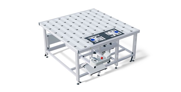
Cleaning station
Transport of the disk through rollers. The operator picks up the unit and pushes it roughly centrally onto the lift table. While the unit is being lifted, it is held by vacuum valves. After reaching the upper table position, the unit can be cleaned. Once the unit is cleared, it goes back down the table and can be pushed to the next table. The position of the table is electrically controlled.
Image 1: Cleaning station
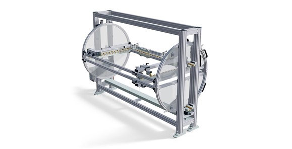
Height-adjustable module holder
The units (maximum weight 175 kg) are moved via a guide equipped with white, tapered POM rollers in the center of the tunnel opening. The height can be adjusted with a hand wheel or e.g. a cordless screwdriver (about 5-7 Nm to lift the system under load); The upper part of the trapezoidal screw used - TR18x4 (above the wheel) has a hex shaft. The retaining system is made with an additional support for the top of the unit to prevent the unit from tipping over.
Image 1: Module holder for flasher tunnel
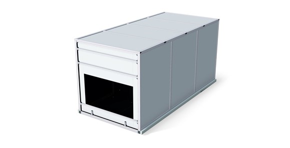
Flasher tunnel
Flasher inlet belt: Transfer of the module from the previous station, provision for flasher section. Flasher middle belt: Transfer of the module from the previous station, provision for flasher. The laminates are always transported to the front in the flasher with a fixed reference position. They are aligned on the inlet belt. The position of the laminate (in the conveyor direction) for the performance test is always in the middle of the flasher. As modules with frames also have to be tested, they are positioned starting from the edge. On moving in the module, the module edge is registered by a sensor. The module is then transported further on an adjustable path on the belt. When the module is positioned, the operator must insert the connection cables into the junction box of the test computer. Automatic contacting is possible with the appropriate box. Flasher outlet belt: Provision of the module for removal from the backend. Flasher tower: Consisting of its MiniTec aluminium profile construction with particleboards, which are inset in the grooves. The inside of the tower is kept matt black to meet the specific requirements of the respective test system manufacturer. The apertures inside the tower are also made to the test system manufacturer’s specifications. The top part of the tower is accessible for maintenance purposes.
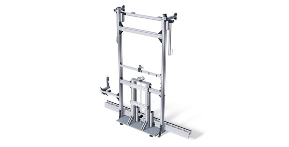
Uprighting station / Cleaning station
Rotating frame with several roller bands (rotation angle ± 90 ° from the original position) fixing in the 3 preset positions (feed position, front control, transport position).
Adjustable stop bar for the different unit lengths, fixing the units to the rotating frame by means of 2 rotating clamps in the corner positions of the unit frame. One of the clamps is permanently mounted, the other on the adjustable stop bar
Exit side roll guide with roll support so units do not catch on cross feed rolls when pushed out.
Image 1: Lifting station/cleaning station
Image 2: Module flip
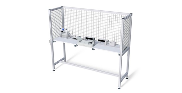
Visual inspection
Transport of pulleys, plates or modules via toothed belt conveyors. Lift and display for visual inspection and cleaning in 2 positions (high and low). Very good, ergonomic accessibility.
To enable a deep, ergonomic presentation, the full carrier is lowered. Includes toothed belt conveyor and protective housing with light barrier secured access area
Image 1: Visual inspection
Image 2: Workstation visual inspection inline for automatic module transport
Glass inspection
Used to automatically save discs. A total of 20 discs can be stored in memory. Discs are also transferred automatically.
Image 1: Glassbuffer FIFO 20 places LEL
Image 2: Glassbuffer LIFO 20 places LEL

Equipment for transporting solar panels

Laser welding machine

Special equipment

Workstations & storage equipment

Additional equipment
SOLUTIONS
Our engineers produce ready-to-use solutions for every job in the construction of plants and special machines for you, based on our profile system. From workstation for assembly, transport and protection systems to fully automated integrated solutions. As a full service provider, we are your trusted partner. From design to implementation to training and support.

Complete Solutions
